Industrial Grade Wireless Vibration and Temperature Sensor, Magnet Mounted

$999.00

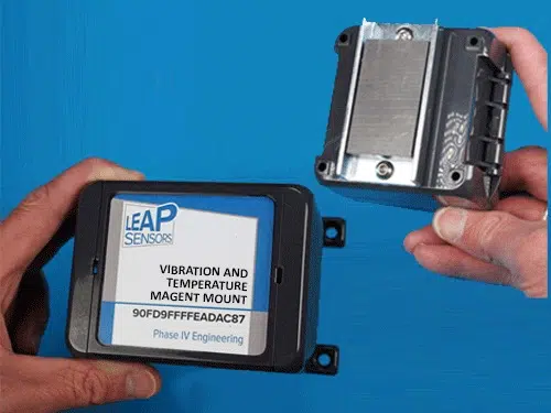
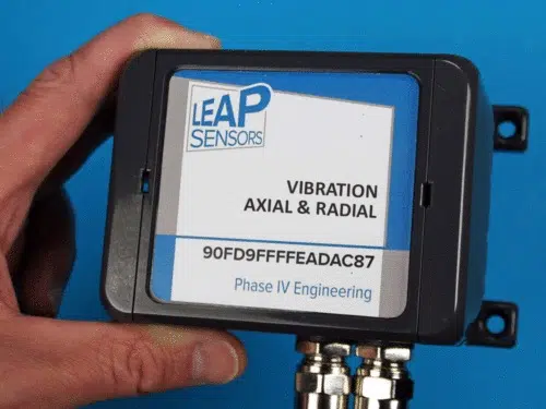
This Leap vibration and temperature device node could not be easier to install.

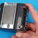
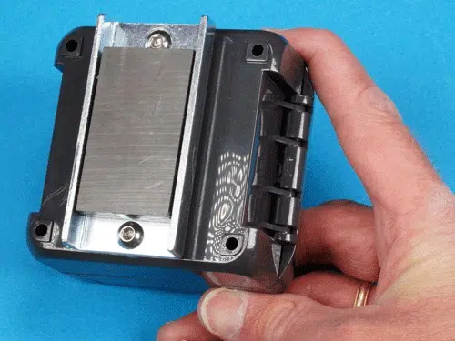
The ultra-strong magnet mounts the device node to the equipment in seconds.  Vibration and temperature is conducted through the magnet to the accelerometer and temperature sensor.

Ideal for monitoring large gearboxes, bearings, and motors to detect impending failures.

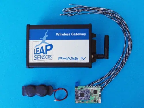
Part of the breakthrough Leap Sensors® system.


Build your quote here:

Add to Quote

Description

Leap Sensors are specially designed to easily adapt to your specific needs. If this isn’t exactly what you need, please contact us.

Wireless Vibration and Temperature Sensor for Predictive Maintenance – Specifications

Designed specifically for monitoring equipment as part of a predictive maintenance program.

  • Monitors the top predictors of impending equipment failures.
    • Motor vibration monitoring sensor detects maximum and average vibration on 3 axis to detect upward trends or spikes in vibration.
    • Motor temperature monitoring sensor detects over-heating.
  • Fast and easy to install.
    • Magnetic mounts the vibration and temperature sensor in seconds.
  • Standard monitoring scenario: Sensor transmits readings every 15 minutes.
    • Temperature alerts are typically set based on normal readings.
    • Vibration is sampled at 5 kHz on 3 axes for a few seconds in the range of 0 to 8Gs.
      • The data is edge-processed on board the sensor using proven methods where a change in trend is indicative of an impending failure.

Temperature Sensing Specification

  • -20C to 85C standard temperature range.
    • Optional high temperature options available with special configurations.  Contact us for more information.
  • Temperature sensor is embedded in the magnet.

Vibration Sensing Specification

  • 3 axis g-force reading taken and edge-processed into RMS acceleration, RMS velocity, and peak acceleration. Any increase in these values indicate a motor is functioning differently and likely has a problem. Each of these readings is calculated for both radial (rotating) vibration and axial vibration (parallel to the shaft of the rotating equipment).
    • RMS acceleration weights the higher frequencies.
    • RMS velocity weights the lower frequencies.
    • Peak acceleration will detect serious impact forces such as bearing defects and chipped gear teeth.
  • G-force readings up to +/- 8 G.
  • Accelerometer operating temperature: -40C to 85C (-40F to 185F)
  • On-board storage for 174,762 sets of 3-axis (x, y, z) g-force samples with 12 bits of resolution.
    • Data is typically processed by a powerful onboard microprocessor using FFT algorithms. Processed vibration analysis is then sent to the transceiver node.
  • Typical sampling and analysis (can be adjusted to each application):
    • Accelerometer is checked every 15 minutes.
    • Each axis is sampled at 5 KHz. (Up to 5 KHz sampling available, if needed).
    • Samples are taken for 3 seconds.
    • RMS acceleration, RMS velocity, and peak acceleration are transmitted.
  • Advanced Fast Fourier Transform (FFT) edge computing available
    • Sensor has a powerful microprocessor and large memory to take vibration samples and process the data at the sensor.
    • Custom edge computing algorithms using FFTs and other sophisticated methods are available.
  • Configurable high G-force event – instant wake-up and transmit function – optional.

Magnet Specification

  • 35 pounds maximum pulling force (on clean steel surface).  Holding force is typically less on surfaces that are painted, dirty, or not flat.
  • 180 F maximum temperature (standard product).  Magnet is 2.75 x 1.12 X 0.5 inches – mounted to the back of the composite enclosure.
    • 390F magnet option available.
  • For non-steel surfaces or surfaces with poor magnetic attraction (such as electric motor fins):
    • Steel sheet metal interface plates are available that come with expoxy to adhere the steel to the desired surface.
  • Not recommended for non-flat surfaces.
  • Contact Us to integrate an application-specific magnet-mounted temperature sensor with the Leap Sensors wireless system.

Leap Wireless Sensor Transceiver Node Specifications

  • Transmission distance to gateway: typically 1500 feet in open air. Several hundred feet in an industrial environment.
  • Battery
  • Bi-color LEDs integrated into the power switch blink to provide user feedback on sensor functions.
  • Rugged sensor enclosure
    • IP68 enclosure rated to 120C (248F). Panel connectors and glands rated to IP68. Power switch with LEDs rated to IP66.
    • Rugged polycarbonate composite enclosure. UL 94 V0 rated, flame-resistant and self-extinguishing.
    • 4.4 x 3.2 x 3.4 in  (113 x 80 x 90 mm), not including optional mounting feet.
  • Long-range antenna inside the enclosure: Keeps the total footprint small and prevents damage to the antenna.
  • Industrial power switch: Latching push button. IP66 rated.
  • Operating temperature: Standard sensor -40C to 85C (-40F to 185F).
    • High operating temperature option available: -40C to 125C* (-40F to 260F). Unique to Leap Sensors.
  • 2-way communication with the sensor through the user interface:
    • Name the sensor (device), set sensor sampling time interval, set wireless transmit time interval, over-the-air firmware updates.
    • Gateways send an acknowledgement to the device that the data was received for high reliability.
  • Sensor data logging: When sensors do not receive an acknowledgement from the gateway that the radio transmission was received, the sensor will store the time-stamped data on-board (up to 10,000 readings) until the gateway connection is established.
  • Reliable industrial over-the-air radio communication
    • Industry-standard 802.15.4 with Direct Sequence Spread Spectrum (DSSS).
    • Gateway “handshake” acknowledgement of successful transmission and sensor data logging for extra reliability.
  • Over-the-air protocol: Standard and established 6LoPan and Thread.
  • Data security: “gold standard” internet security with AES encryption.
  • FCC certified.

Leap Wireless Sensors Gateway (Receiver) and User Interface Software

  • See the Leap Sensors gateway page and the Leap Sensors User Interface options page for more detailed information.
  • Leap Sensors wirelessly transmit data to a gateway*.
    • Gateway can support over 250 sensors that are in range. (Additional gateways can extend sensor coverage.)
    • The gateway then passes the data to the Leap user interface software. The user interface software may be hosted on the gateway (and connected to a PC with a USB cable), on the password-protected Leap Sensors Cloud web site, or an on-site server.
  • User interface supports: logging-in, set user rights, view sensor data, set email and text alerts (cloud version), graph sensor data, download data to excel, add or subtract sensors, update firmware, and other functions.

*Custom-ordered leap sensors are available with a direct-to-cellular option where no gateway is needed and the data is sent directly to a cloud server. Contact us for more information.

Contact Us

Prices, Quotes, Questions...

Need a price or quote? Have questions? Want to talk to an expert? Need a custom solution?

Contact Us

This wireless sensor is ideal for monitoring:

  • Gearbox monitoring
  • Motor monitoring
  • Equipment overheating
  • Large bearings

Patents pending.

Go to Top